

Quick Trade Summary: Y-Strainers in UK Plumbing & Heating Systems
A Y-strainer is an inline mechanical filtration fitting designed to remove solid debris—such as pipe scale, solder swarf, sand, welding slag, and installation grit—from fluid systems using a perforated cylindrical or wire-mesh stainless steel filter element:
- Core Purpose: Protects high-value hydraulic equipment—including heat pump brazed plate heat exchangers (BPHEs), boiler primary heat exchangers, circulation pumps, thermostatic mixing valves (TMVs), and pressure reducing valves (PRVs)—from catastrophic blockage and mechanical abrasion.
- Standard Mesh Ratings: Domestic and commercial hydronic heating systems typically utilise 20 to 80 mesh (180 to 840 microns), with 500-micron screens standard on heat pump return loops.
- Installation Orientation: In horizontal pipe runs, the Y-leg filter chamber must always point downwards (at a 45° angle) to allow gravity to trap particulate. In vertical runs, installation is only permissible where flow is strictly downwards.
- UK Standards & Compliance: Essential for compliance with BS 7593:2019 (Water Treatment for Wet Central Heating Systems), BS EN 1254 (Copper & Brass Fittings), and CIBSE Commissioning Code W.
Mechanical Anatomy and Operating Principles of a Y-Strainer
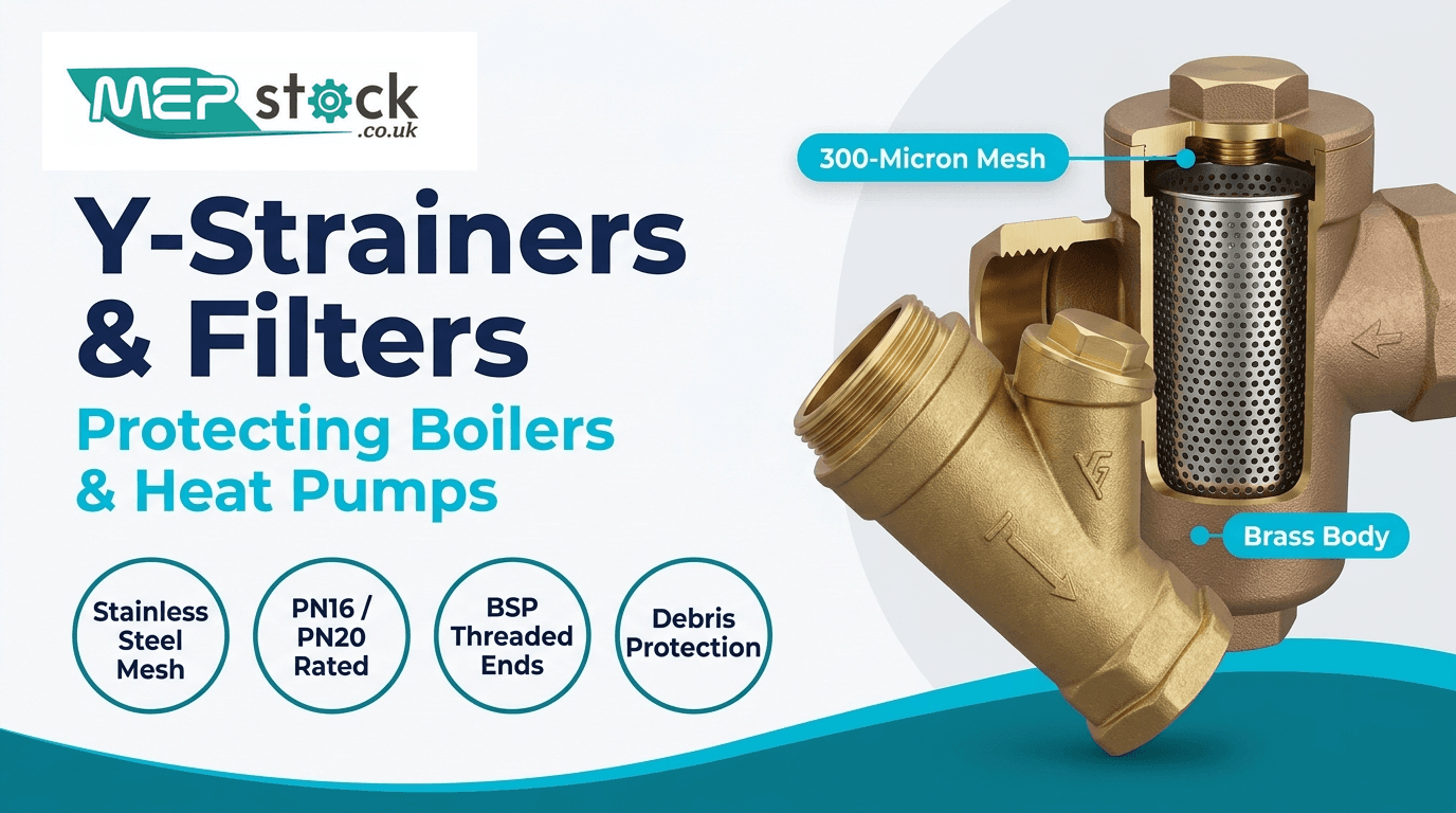
A Y-strainer derives its name from its distinctive "Y" shaped casting geometry. It consists of a primary flow passage with an intersecting side chamber positioned at an acute angle (typically 45° or 60°). Inside this angled branch sits a removable, cylindrical cylindrical filter screen basket made of 304 or 316-grade stainless steel.
As fluid enters the inlet port of the strainer, it is directed into the interior chamber of the stainless steel screen basket. The fluid passes outward through the calibrated perforations or wire mesh, while solid particles larger than the screen apertures are mechanically captured inside the basket or settle into the lower collection pocket of the Y-branch.
Key Engineering Components of a Quality Y-Strainer:
- Body Casting: High-grade Dezincification Resistant (DZR) Brass (CW602N), Bronze (LG2 Gunmetal), Cast Iron, or CF8M 316 Stainless Steel rated for PN16 to PN25 working pressures.
- Strainer Screen Basket: Heavy-gauge stainless steel (grade 304 or 316) offering high collapse strength against differential pressure spikes ($\Delta P$).
- Bonnet / Service Cap: Threaded hexagonal brass or bronze end cap allowing rapid access to the filter basket without breaking pipe connections.
- Bonnet Gasket: High-temperature EPDM, PTFE (Teflon), or NBR sealing ring preventing external leakage under high thermal cycling.
- Blow-Off / Drain Port (Optional): A threaded plug or integrated mini ball valve on the cap for high-velocity flushing of trapped particulates during operation.
Y-Strainer vs Magnetic System Filter vs Dirt Separator: Which Do You Need?
A common misconception among heating engineers and plumbers is that a high-capacity magnetic boiler filter replaces the need for a mechanical Y-strainer. In reality, these devices perform fundamentally different filtration tasks, and modern high-efficiency systems—especially Air Source Heat Pumps (ASHPs)—require both to satisfy manufacturer warranty terms and BS 7593:2019 standards.
| Feature / Metric | Inline Y-Strainer | Magnetic Filter (e.g. Adey / Fernox) | Vortical Dirt Separator (e.g. Spirotech) |
|---|---|---|---|
| Primary Target Debris | Coarse mechanical solids (sand, flux residue, copper swarf, scale flakes, PTFE fragments). | Microscopic ferrous magnetite black sludge ($Fe_3O_4$). | Non-magnetic micro-dirt, circulating silt, and micro-air bubbles. |
| Particle Size Range | 100 μm to 1,000+ μm (Mechanical Mesh) | 0.5 μm to 50 μm (High-Gauss Neodymium Magnet) | 5 μm to 100 μm (Spirotube Cyclonic Action) |
| Pressure Drop (ΔP) | Low when clean (0.05–0.15 bar); increases significantly when blocked. | Negligible (Full-flow bypass design). | Extremely low and constant across service life. |
| Optimal Location | Directly before sensitive equipment (pumps, PRVs, heat pump heat exchangers). | Boiler / Heat Pump return line, upstream of heat source. | System return header before primary circulation pump. |
| Cleaning / Servicing | Requires system isolation, cap removal, and manual basket wash. | Quick magnet removal and drain valve flush (tool-free). | Fast bottom drain flush during normal system pressure. |
Micron to Mesh Conversion: Selecting the Correct Filter Screen
Filter screens are specified using either Mesh Count (the number of openings per linear inch) or Microns (μm) (the exact physical dimension of the opening, where 1 micron = 0.001 mm). Selecting the wrong screen mesh can either lead to uninhibited debris passing through or cause rapid clogging and severe hydraulic cavitation.
| Mesh Size | Aperture (Microns μm) | Opening (Inches / mm) | Recommended Application |
|---|---|---|---|
| 20 Mesh | 840 μm | 0.033" / 0.84 mm | Raw mains water intake, rainwater harvesting, heavy industrial supply. |
| 40 Mesh | 420 μm | 0.016" / 0.42 mm | Domestic Central Heating & ASHP Return Lines (Standard protection for plate heat exchangers). |
| 60 Mesh | 250 μm | 0.010" / 0.25 mm | Solar thermal glycol circuits, commercial fan coils, fine pressure reducing valves. |
| 80 Mesh | 177 μm | 0.007" / 0.18 mm | Chilled water fan coils, precision metering orifices, laboratory water feeds. |
| 100 Mesh | 149 μm | 0.006" / 0.15 mm | Fine misting nozzles, hydraulic instrumentation, ultra-pure water loops. |
Hydraulic Sizing, Flow Rates ($K_v$ Values) & Pressure Drop Calculations
When sizing a Y-strainer for a closed-loop hydronic system, pipe diameter is only one factor; the critical engineering variable is the flow coefficient ($K_v$), representing the volume of water in $m^3/h$ at 20°C that will pass through the valve with a pressure loss of 1 bar:
Pressure Drop Formula: ΔP = (Q / K_v)² × SG
Where ΔP is pressure drop in bar, Q is flow rate in $m^3/h$, K_v is valve flow capacity, and SG is specific gravity of fluid (1.0 for pure water, ~1.03 for 30% glycol).
| Nominal Size (DN / BSP) | Copper Pipe Size (mm) | Clean Screen $K_v$ ($m^3/h$) | Max Recommended Flow ($m^3/h$) | Typical ΔP at Peak Flow |
|---|---|---|---|---|
| 1/2" (DN15) | 15 mm | 3.2 | 0.9 | 0.08 bar (0.8 mWG) |
| 3/4" (DN20) | 22 mm | 5.8 | 1.8 | 0.10 bar (1.0 mWG) |
| 1" (DN25) | 28 mm | 9.6 | 3.2 | 0.11 bar (1.1 mWG) |
| 1-1/4" (DN32) | 35 mm | 17.5 | 5.5 | 0.10 bar (1.0 mWG) |
| 1-1/2" (DN40) | 42 mm | 25.0 | 8.5 | 0.12 bar (1.2 mWG) |
| 2" (DN50) | 54 mm | 41.0 | 14.0 | 0.12 bar (1.2 mWG) |
Air Source Heat Pumps (ASHPs): Why Heat Exchangers Require Y-Strainers
Unlike traditional gas boilers with relatively wide waterway channels, modern high-efficiency heat pumps utilise ultra-compact Brazed Plate Heat Exchangers (BPHEs) to transfer heat between the refrigerant circuit and the hydronic central heating circuit.
These microchannel plates have inter-plate clearances as narrow as 1.5 mm to 2.5 mm. If construction debris, soldering slag, copper filings, or hard lime scale enter the evaporator or condenser plate channels:
- Channel Starvation: The constricted plate channels become physically blocked, reducing effective surface area and causing severe heat transfer loss.
- Refrigerant Freezing & Plate Rupture: In cooling or low-ambient heating modes, starved water channels freeze, expanding and causing internal refrigerant-to-water plate rupture—a catastrophic failure resulting in total compressor destruction.
- Loss of Warranty: Leading heat pump manufacturers (including Daikin, Mitsubishi, Vaillant, and Samsung) explicitly mandate a sub-500 micron Y-strainer on the return pipe directly upstream of the outdoor monobloc or indoor hydrobox. Failure to fit one invalidates the compressor warranty.
Critical Installation Rules and Orientation Best Practices
A Y-strainer must be correctly oriented with respect to both water flow direction and gravity. Incorrect installation will result in collected dirt falling back into the flow stream or jamming the main waterway.
Horizontal Pipe Installations
The Y-chamber screen leg must point downwards at a 45° angle below the pipe centerline. This creates a gravity collection sump where debris drops naturally out of the primary velocity stream. Never install a Y-strainer with the leg pointing upwards, as dirt will remain in the pipe bore.
Vertical Pipe Installations
Vertical installation is strictly permitted only when the fluid flow is downwards. In downward flow, gravity and water velocity work together to sweep debris into the filter basket. Never install a Y-strainer on a vertical pipe with upward flow, as particles will settle on top of the pump below.
Essential Installation Checklist:
- Arrow Direction: Always verify the cast arrow on the brass body points in the exact direction of fluid flow.
- Isolation Valves: Fit full-bore lever ball valves immediately upstream and downstream of the Y-strainer to allow rapid basket servicing without draining the entire heating circuit.
- Maintenance Clearance: Ensure at least 150mm of clear space below the hexagonal bonnet cap to allow the filter basket to be withdrawn smoothly for cleaning.
Step-by-Step Servicing and Cleaning Workflow
Under BS 7593:2019, Y-strainers should be inspected and cleaned during initial system commissioning (after 24 hours of dynamic flushing) and during annual heating maintenance. Follow this professional trade protocol:
- Isolate the Line: Close both the upstream and downstream full-bore isolation ball valves. Turn off the boiler or heat pump circulation pump.
- Depressurise: Place a collection tray or bucket beneath the Y-chamber. Carefully loosen the bonnet plug or cap by half a turn using an adjustable wrench or hex socket to release trapped hydrostatic pressure.
- Extract Basket: Completely unthread the hexagonal bonnet cap. Pull out the stainless steel filter screen basket.
- Inspect & Clean: Inspect the mesh for signs of physical tearing or calcium scale build-up. Wash the basket thoroughly under clean running water, using a soft nylon brush to dislodge trapped solder beads and copper swarf. For stubborn magnetite or limescale, soak in mild descaler.
- Check Gasket Seal: Examine the EPDM/PTFE sealing ring on the bonnet cap. If compressed, brittle, or cracked, replace with a fresh O-ring seal to prevent post-service weeping.
- Reassemble & Purge: Re-insert the screen basket, ensuring it seats firmly into the body guide groove. Thread the bonnet cap and tighten firmly (do not over-torque brass castings). Open isolation valves slowly and inspect for leaks under full operating pressure.
Commercial Quality Y-Strainers & System Heating Filters
BS EN 1254 compliant, DZR brass, stainless steel mesh, and WRAS approved fittings for UK plumbing and heating systems.
Brass BSP Y-Strainer Valves
Dezincification-resistant brass body with 304 stainless steel screen. Available in 1/2" to 2" BSP female threads. PN20 rated.
Full-Bore Lever Ball Valves
Heavy-duty WRAS approved full-bore isolation valves for zero flow restriction upstream and downstream of filter banks.
M-Profile Press Fittings
BS EN 1254-7 approved copper press fittings and adaptors for rapid flame-free connection to boiler and heat pump headers.
Frequently Asked Questions (FAQs)
Can a Y-strainer be installed on the supply / flow pipe instead of the return?
While a Y-strainer can technically be installed on the flow pipe to protect downstream zone valves or underfloor heating manifolds, best practice dictates installing it on the return pipe immediately prior to the heat source or circulating pump. This ensures that any debris circulating from old radiators or pipework is captured before it can enter the delicate heat exchanger or pump impeller.
How often does a Y-strainer need to be cleaned?
On newly commissioned systems, the Y-strainer should be cleaned within 24 to 48 hours of initial circulation, as this is when construction swarf, flux, and loose scale are mobilized. Thereafter, screen cleaning should be performed annually alongside scheduled boiler/heat pump servicing. If pressure drops or circulation flow fault codes occur, inspect the screen immediately.
What is the difference between a perforated screen and a wire mesh screen?
A perforated screen consists of a solid sheet of stainless steel with punched holes (typically 0.8mm to 3.0mm diameter), offering exceptional structural strength against high differential pressure. A wire mesh screen uses woven stainless steel wires to achieve much finer filtration (down to 50–250 microns). For fine filtration, a mesh screen is often supported inside a perforated cylinder to prevent collapse under load.
Are Y-strainers suitable for glycol / antifreeze mixtures in heat pump systems?
Yes. Quality brass and bronze Y-strainers fitted with EPDM or PTFE bonnet seals are fully compatible with propylene glycol and ethylene glycol solutions up to 50% concentration. Ensure the $K_v$ rating of the strainer accounts for the slightly higher viscosity and specific gravity of glycol mixtures to prevent unnecessary pump head loss.