

Quick Installer Summary: Underfloor Heating Flow Rate Calculations & Balancing
Hydraulic balancing of an underfloor heating (UFH) manifold is required to ensure that every circuit delivers the exact thermal output required by the room design without starving distant loops or causing velocity noise. Key trade rules include:
-
The Fundamental Flow Equation: Flow rate in litres per minute is calculated using
V (L/min) = Q (Watts) / (70 × ΔT), where ΔT is the design temperature differential between flow and return. -
Quick Rule-of-Thumb Estimation: For rapid on-site commissioning, divide the continuous pipe loop length in metres by 40 (
L/min ≈ Circuit Length (m) / 40). For example, an 80-metre loop requires approximately 2.0 L/min. - Heat Pump vs Boiler ΔT: Heat pump underfloor heating systems operate on a tight ΔT of 5°C (5K), requiring double the flow rate (typically 1.5 to 3.0 L/min per loop) compared to traditional condensing boilers operating on a ΔT of 10°C (0.8 to 1.5 L/min).
- Maximum Loop Constraints: Keep standard 16mm PERT-AL-PERT pipe coils to a maximum of 100m–110m. Loops exceeding 110m create excessive hydraulic resistance (>25 kPa) that standard circulator pumps cannot overcome.
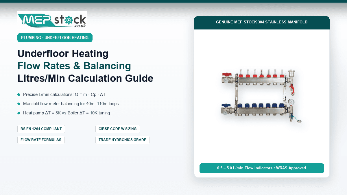
- Manifold Flow Meter Setting: Calibrate flow indicators on the supply rail of a Stainless Steel UFH Manifold by rotating the red locking collar until the bottom edge of the black indicator float aligns precisely with the calculated L/min marker.
Why Precision Flow Rate Balancing Is Critical in Underfloor Heating
Unlike conventional radiator systems where thermostatic radiator valves (TRVs) modulate local output based on instantaneous air temperature, hydronic underfloor heating is an embedded thermal mass system. Water travels through tens of metres of continuous composite pipe encased within concrete screed, dry screed boards, or timber joist plates.
Water naturally follows the path of least hydraulic resistance. In an uncalibrated manifold, water will rush through short circuits (such as a 35-metre hallway or en-suite loop) while starving longer, high-demand circuits (such as a 95-metre open-plan kitchen or living room loop). The consequence is severe thermal stratification: small rooms overheat rapidly while main living zones remain cold, regardless of how high the master boiler thermostat is turned.
By balancing individual manifold circuit flow meters according to BS EN 1264 and CIBSE Code W guidelines, heating engineers set mechanical proportional resistance across every loop. This guarantees balanced heat delivery, prevents short-cycling of heat sources, and eliminates turbulent water hiss inside manifold cabinets.
The Physics and Mathematics of Underfloor Heating Flow Rates
To calculate the exact volume of water that must pass through an underfloor heating loop every minute, heating engineers use the fundamental thermodynamic heat transfer formula:
Where:
- Q: Thermal heat output required for the zone in Watts (W).
- &mHost;: Mass flow rate of the heat transfer fluid in kilograms per second (kg/s).
- Cp: Specific heat capacity of water (4,184 J/kg·K at 40°C).
- ΔT: Temperature differential between the flow rail water temperature and return rail water temperature (in Kelvin or °C).
Deriving the Litres Per Minute (L/min) Trade Formula
Converting mass flow rate from kilograms per second into practical volumetric flow rate in litres per minute (L/min) for water (density ≈ 1.0 kg/L) yields the standardized engineering equation:
This constant 70 is the standard industry multiplier used across UK hydronic commissioning.
Flow Rate Sizing Matrix: Room Heat Load vs Design Temperature Differential (ΔT)
The required flow rate is inversely proportional to the design temperature differential (ΔT). The table below outlines the precise flow rate settings in litres per minute required for standard room heat loads under both heat pump (ΔT = 5K) and condensing boiler (ΔT = 10K) operating regimes:
| Room Heat Load (Watts) | Typical Room Type & Floor Area | Heat Pump Flow Rate (ΔT = 5K) | Boiler Flow Rate (ΔT = 10K) | Recommended 16mm Loop Length |
|---|---|---|---|---|
| 350 W | En-Suite / Small WC (5m²) | 1.0 L/min | 0.5 L/min | 30m – 40m |
| 700 W | Double Bedroom / Study (10m²) | 2.0 L/min | 1.0 L/min | 60m – 70m |
| 1,050 W | Master Bedroom / Dining (15m²) | 3.0 L/min | 1.5 L/min | 80m – 90m |
| 1,400 W | Open Plan Kitchen / Lounge (20m²) | Split into 2 × 2.0 L/min | 2.0 L/min | 2 × 65m loops |
| 2,100 W | Large Ground Floor Zone (30m²) | Split into 3 × 2.0 L/min | Split into 2 × 1.5 L/min | 3 × 70m loops |
Hydraulic Pressure Drop and Pipe Resistance Calculations
Flow rate cannot be considered in isolation from hydraulic friction. As water moves through 16mm × 2.0mm PERT-AL-PERT composite pipe (which has an internal diameter of 12.0mm), frictional resistance against the internal polyethylene walls creates a measurable pressure drop (Δp).
According to the Darcy-Weisbach equation for smooth polymer tubes, velocity should remain between 0.3 m/s and 0.8 m/s. Velocities below 0.3 m/s fail to carry away entrained micro-air bubbles to the automatic air vent, while velocities above 0.8 m/s create audible water turbulence and excessive pump power consumption.
| 16mm Loop Length | Flow Rate (L/min) | Water Velocity (m/s) | Total Loop Resistance (kPa) | Pump Head Required (mH2O) |
|---|---|---|---|---|
| 40 Metres | 1.2 L/min | 0.28 m/s | 4.2 kPa | 0.43 m |
| 70 Metres | 2.0 L/min | 0.47 m/s | 12.8 kPa | 1.31 m |
| 90 Metres | 2.5 L/min | 0.59 m/s | 21.6 kPa | 2.20 m |
| 120 Metres (Exceeded) | 3.0 L/min | 0.71 m/s | 38.4 kPa | 3.92 m (Pump Strained) |
Step-by-Step Manifold Flow Meter Adjustment Workflow
Modern Stainless Steel Distribution Manifolds are equipped with integrated Taconova-style mechanical sight flow meters mounted along the top supply bar. To commission the manifold to your calculated flow rates, follow this systematic procedure:
Commissioning & Calibration Sequence:
- Energise the Circulator Pump: Set the manifold mixing pump or primary system circulator to Constant Pressure (Δp-c) mode (Curve 2 or 3). Do not use Proportional Pressure or AutoAdapt during manual flow meter calibration.
- Open All Circuit Actuators: Remove electrothermic actuators or manually screw on manual blue commissioning caps and back them off fully counter-clockwise to ensure all return ports are 100% open.
- Unlock the Flow Meter Locking Collar: Lift or twist the red locking collar at the base of the transparent flow meter glass cylinder on Port 1.
-
Rotate to Adjust Indicator Float: Rotate the black knurled body or the glass sight barrel:
- Rotating Counter-Clockwise (Anti-Clockwise): Opens the internal valve spindle, increasing flow rate.
- Rotating Clockwise: Restricts the aperture, decreasing flow rate.
- Read the Bottom Edge of the Float: Look horizontally across the clear glass sight tube. The correct reading corresponds to where the bottom flat edge of the black or red indicator disc aligns with the printed measurement scale (0.5 to 5.0 L/min).
- Re-Lock and Settle: Push the red locking collar down to lock the setting. Work sequentially from the longest circuit to the shortest circuit, then perform a final secondary check across all meters once the hydraulic network settles.
Common Flow Rate Imbalances and Troubleshooting
Symptom 1: Flow Meter Float Does Not Move or Reads Zero
If an individual circuit shows 0 L/min despite the pump running and the flow meter being opened fully, check the following common causes:
- Air Lock in Circuit: The loop contains entrained air pockets blocking hydraulic flow. Purge the individual loop with mains water pressure through the manifold drain valve until water flows completely bubble-free.
- Stuck Pin on Return Valve: Electrothermic actuator ports on the bottom rail contain an internal spring-loaded brass pin. If an actuator was left closed for months, the pin may stick down. Remove the actuator and gently depress the pin with a flat tool until it springs freely.
- Reversed Flow/Return Connections: If flow enters the bottom manifold rail instead of the top, sight flow meters will not register flow properly. Verify that hot primary water enters the top bar fitted with red isolation valves.
Symptom 2: Flow Rate Drops When Other Zones Open
If setting 2.5 L/min on Circuit 1 causes Circuit 2 to drop from 2.0 to 1.2 L/min, the total hydraulic capacity of the circulator pump is insufficient to overcome overall system head loss, or primary distribution pipework is undersized. For systems over 6 ports, ensure primary feed pipework is at least 28mm copper or 32mm MLCP with Full Bore 1-inch Lever Ball Valves to eliminate primary throttling.
Upgrade Your Hydronic Installations with Genuine MEP Stock Manifolds & Pipe
Get precision-engineered 304 Stainless Steel Manifolds with calibrated 0.5–5.0 L/min flow meters, commercial-grade mixing pump packs, and WRAS-approved PERT-AL-PERT pipe coils with guaranteed next-day UK delivery.
Frequently Asked Questions About Underfloor Heating Balancing
What is the ideal flow rate for a 16mm underfloor heating loop?
For standard residential rooms with loop lengths between 60m and 80m, the optimal flow rate is 2.0 litres per minute (L/min) on a heat pump system (ΔT = 5K) or 1.0 to 1.2 L/min on a gas condensing boiler (ΔT = 10K).
Can an underfloor heating loop be too long?
Yes. The maximum recommended continuous loop length for 16mm MLCP is 100 metres (maximum 110m including manifold tails). Loops longer than 110m create excessive pressure drops exceeding 25–35 kPa, resulting in severe heat loss along the circuit and cold floor sections near the return rail.
Should flow meters be installed on the flow or return manifold bar?
Standard mechanical sight flow meters are calibrated for positive water pressure and must always be installed on the top flow (supply) manifold rail. The bottom return rail is reserved for electrothermic actuators or manual lockshield valves.