

Quick Installer Summary
- Automatic Air Vents (AAVs): Designed strictly for venting large, free pocketed air during system commissioning and routine high-point collection. AAVs cannot strip entrained microbubbles or dissolved oxygen from circulating water.
- Microbubble Deaerators (e.g., SpiroVent / SpiroCross): Installed directly on the hottest main flow pipework before system distribution to continuously extract microbubbles (<0.05mm) and force dissolved gas release via Henry's Law degassing.
- BS 7593:2019 & CIBSE Compliance: Modern condensing boilers and high-flow heat pump circuits require both high-point AAVs and an inline mechanical deaerator/dirt separator to stop pump impeller cavitation, heat exchanger kettling, and black iron oxide (magnetite) sludge formation.
- Location Rule: AAVs belong at static hydraulic peaks (manifold tops, riser tops); Deaerators belong at the point of lowest gas solubility—the hottest boiler/heat pump primary flow header immediately upstream of the circulator.
Fundamental Hydronic Physics: Free Air vs Dissolved Gases
In closed-loop hydronic heating and cooling systems, air exists in three distinct thermodynamic states: free air pockets, entrained microbubbles, and dissolved gas molecules. Failing to distinguish between these states leads to recurring radiator cold spots, erratic flow meter readings on underfloor heating manifolds, noisy circulator impellers, and severe electrolytic corrosion.
When fresh tap water fills a heating circuit, it contains roughly 20 to 30 litres of dissolved air per cubic metre (1,000L) of water at 10°C and 1.5 bar. This air consists of approximately 78% nitrogen and 21% oxygen. The behaviour of these dissolved gases is governed by Henry's Law, which dictates that the solubility of a gas in a liquid is directly proportional to the partial pressure of the gas above the liquid and inversely proportional to the liquid temperature:
Where C = dissolved gas concentration (mol/L), k_H = Henry's law constant (decreases as temperature rises), and P_gas = system static pressure.
As circulating water enters a primary heat exchanger and heats from 20°C to 55°C (in heat pumps) or 75°C (in gas boilers), Henry's constant drops dramatically. The water becomes super-saturated with air. Millions of microscopic gas bubbles (<0.1 mm in diameter) precipitate out of solution at the hottest internal heat transfer surfaces. These microbubbles do not rise quickly to high-point AAVs because the circulating water velocity (typically 0.8 to 1.5 m/s) easily overcomes their buoyancy force.
Stokes' Law and Why Automatic Air Vents Cannot Catch Microbubbles
An Automatic Air Vent (AAV) relies on static fluid buoyancy. Inside an AAV chamber, an internal polypropylene or brass float drops when air displaces water, opening a spring-loaded or needle valve seat to exhaust air to the atmosphere. However, for a bubble to enter an AAV, its upward terminal rise velocity must be greater than the horizontal drag velocity of the circulating fluid.
According to Stokes' Law, the terminal rising velocity \(v\) of a spherical bubble in a fluid is proportional to the square of its radius:
Where r = bubble radius, ρ = density, g = gravitational acceleration, and μ = dynamic viscosity of water.
A macroscopic air pocket (diameter > 5 mm) rises at velocities exceeding 0.2 m/s, easily floating into an AAV chamber when the pump stops or at low-velocity riser headers. Conversely, a microbubble (diameter < 0.05 mm) has a rise velocity of less than 0.001 m/s (1 millimetre per second). When moving through a 22mm or 28mm copper or MLCP primary pipe at 1.0 m/s, microbubbles are swept straight past an AAV tee without ever rising into the vent chamber.
Equip Your Plantrooms with Genuine MEP Stock Hydronic Valves
Discover trade-grade automatic air vents, full bore isolation lever valves, brass strainers, and WRAS-approved plantroom fittings engineered for maximum heating efficiency.
Shop Air Vents & Plantroom Fittings →How Microbubble Deaerators Work: Coalescence and Wire Mesh Geometry
A microbubble deaerator is an inline hydraulic separation vessel designed to decelerate the flow velocity and promote microbubble coalescence. The internal geometry features a specialised concentric wire mesh basket, Pall rings, or copper Spiro-tubes.
The deaeration process follows a three-stage mechanical sequence:
- Flow Velocity Reduction: The enlarged body of the deaerator (typically 3 to 4 times the pipe diameter) causes the fluid velocity to drop below 0.15 m/s according to the continuity equation \(Q = A \cdot v\).
- Surface Coalescence: Microbubbles entrained in the stream collide with the intricate wire mesh surfaces. The jagged edges break fluid surface tension, causing microscopic bubbles to adhere, merge, and coalesce into larger macroscopic air pockets.
- Buoyancy Release: Once the bubbles coalesce to a diameter where their buoyancy overcomes the reduced downward fluid drag, they rise rapidly into the quiet deaeration chamber at the top of the vessel, where an automatic air release mechanism exhausts them permanently.
Continuous circulation through a microbubble deaerator creates unsaturated (degassed) water throughout the system. When this degassed water travels out into cooler remote radiators and underfloor heating loops, it acts as an active sponge, dissolving static air pockets trapped in pipe coils and transporting them back to the boiler room for removal.
Corrosion Chemistry: Dissolved Oxygen and Magnetite Formation
The primary driver of hydronic system degradation across the UK is dissolved oxygen corrosion. In the presence of free oxygen (\( ext{O}_2\)), mild steel radiators, cast iron pump volutes, and carbon steel pipework undergo aggressive electrochemical oxidation:
3 Fe + 4 H_2O → Fe_3O_4 + 4 H_2 (Black Magnetite Sludge + Hydrogen Gas)
When an installation relies solely on standard AAVs, dissolved oxygen remains in circulation. Under thermal cycling, it oxidises iron surfaces into black magnetite sludge (\( ext{Fe}_3 ext{O}_4\)). This sludge sticks inside plate heat exchangers, jams variable-speed ECM circulator rotors, and blocks narrow underfloor heating manifold flow meters.
By installing an inline microbubble deaerator combined with a magnetic dirt separator compliant with BS 7593:2019, dissolved oxygen levels are reduced below 0.05 mg/L, virtually halting internal corrosion reactions without excessive chemical dosing.
Heat Pump Protection: Preventing Circulator Cavitation and Delta T Instability
Air management is even more critical in modern air-to-water heat pump installations operating at low design temperatures (flow 35°C – 45°C, \(\Delta T = 5 ext{K}\)). Heat pumps require volumetric flow rates 2.5 to 3 times higher than equivalent gas boiler systems (\(1,800 - 2,500 ext{ L/h}\)).
At these elevated flow velocities, tiny microbubbles passing through the suction eye of an ECM circulator experience a sharp local static pressure drop below the vapour pressure of water \(P_v\), triggering acoustic cavitation:
Where σ = Cavitation Index. When σ drops below critical thresholds, bubble collapse erodes pump impellers and causes severe flow disruption.
Microbubble deaeration eliminates the gas nucleation seeds that trigger cavitation, ensuring laminar flow across heat pump heat meters, silent pump operation, and stable \(\Delta T\) heat transfer.
Installation Locations: Where to Fit AAVs vs Deaerators
| Device Type | Ideal System Location | Operational Function | Key Precautions |
|---|---|---|---|
| Automatic Air Vent (AAV) | Highest physical points: top of vertical distribution risers, underfloor heating manifold flow/return rails, above boiler heat exchangers. | Venting bulk air pockets during initial filling and commissioning. | Always install with an automatic check valve / service valve. Screw dust cap tight after commissioning to prevent accidental leaks. |
| Microbubble Deaerator | Hottest point of the system: on the primary flow pipe immediately exiting the boiler or heat pump, before the circulator and distribution headers. | Continuous extraction of microscopic bubbles (<50μm) and chemical degassing of circulating fluid. | Must be sized for system design flow rate (m³/h) to keep internal velocity within laminar deaeration range (<1.0 m/s). |
Trade Best Practice: AAV Maintenance & Leak Prevention
A common complaint among plumbing contractors is AAV leakage over time. In untreated systems, circulating particulate debris and lime scale settle onto the delicate rubber seal of the float needle. When the float drops to vent air, grit lodges on the seat, preventing full closure and causing water weeping.
To eliminate AAV callbacks:
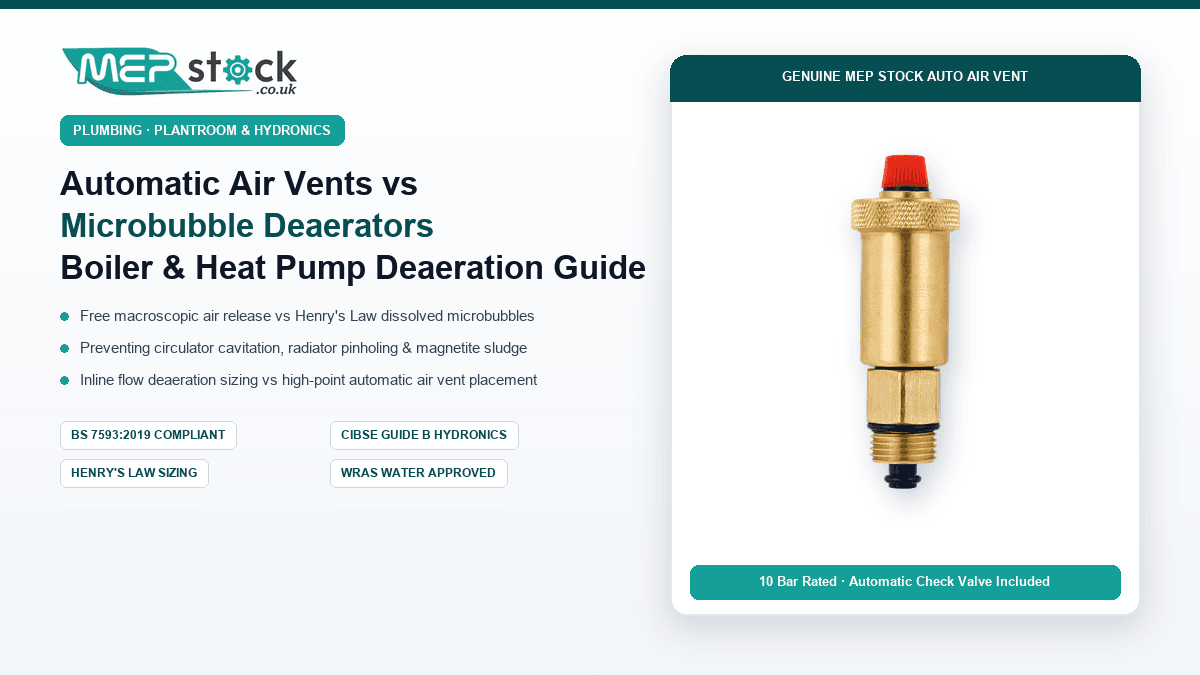
- Always Use Integrated Check Valves: Specify AAVs with self-sealing check valves (like the MEP Stock ½″ brass AAV). This allows the entire vent body to be unscrewed and cleaned or replaced without draining the heating circuit.
- Commission with Open Caps, Run with Sealed Caps: Leave the knurled hygroscopic vent cap backed off by one turn during power flushing and initial heat-up. Once commissioning is complete and bulk air is evacuated, hand-tighten the cap to eliminate leak risks in finished living areas.
- Pair with Chemical Inhibitor (BS 7593): Dose the system with buildcert-approved corrosion inhibitor to prevent scale deposition on internal float hinges.
Upgrade Your Heating Installations with MEP Stock
Explore our comprehensive range of WRAS-approved automatic air vents, full bore isolation valves, UFH manifolds, and high-performance MLCP pipework at unbeatable trade prices.
Shop Full Trade Catalogue →