

Quick Installer Summary
When an underfloor heating blending valve is not getting hot, the fault almost always traces back to one of four hydraulic causes: a seized thermostatic wax element, reversed primary flow/return connections, trapped air inside the pump volute, or a closed/jammed non-return check valve. Under BS EN 1264, mixed flow temperatures must sit between 35°C and 55°C depending on the floor finish, with a design temperature drop (ΔT) of 5°C to 10°C across the manifold loops.
- Target Mixed Flow: 45–50°C (Tile/Stone), 38–42°C (Engineered Wood), 35–40°C (LVT/Vinyl).
- Primary Supply Requirement: Boiler flow must be at least 10°C–15°C hotter than the desired UFH mixed setpoint.
- Standard UK Replacement Centres: 210mm manifold centres with 1" BSP unions (direct fit for Grundfos UPM3 & Wilo Para packs).
A cold underfloor heating (UFH) manifold is one of the most common call-outs UK heating engineers face during winter commissioning and servicing. You arrive on site, the boiler is firing at 70°C, the primary feed pipe entering the mixing unit is scalding hot, yet the top flow bar on the manifold reads a lukewarm 25°C and the floors stay stone cold.
Understanding the exact thermodynamics and internal mechanics of a thermostatic mixing unit allows you to pinpoint whether the issue is a simple airlock, a misconfigured dial, or a failed wax capsule requiring a full Underfloor Heating Blending Valve and Pump Set (20°C–55°C) replacement. This comprehensive engineering guide covers hydraulic mixing physics, BS EN 1264 floor temperature limits, step-by-step fault diagnostics, and direct replacement protocols.
How a Thermostatic Underfloor Heating Blending Valve Works
Gas and oil boilers typically operate at flow temperatures between 65°C and 80°C to satisfy radiator heat-loss schedules and domestic hot water cylinders. Pumping 75°C water directly into a screeded floor slab would cause severe thermal shock, cracking the screed, delaminating LVT adhesives, and warping engineered timber.
The UFH blending valve acts as a proportional three-port thermostatic mixer. Internally, a temperature-sensitive wax element expands and contracts in response to the blended water temperature exiting the valve toward the circulation pump:
- Hot Port (Primary Flow): Draws high-temperature water from the boiler primary circuit (up to 90°C).
- Cold Port (Manifold Return): Recirculates cooler water returning from the floor loops (typically 30°C–38°C).
- Mixed Port (Manifold Flow): Delivers constant-temperature blended water (20°C–55°C) into the A-rated circulation pump and across the flow-meter bar.
The heat output delivered to the floor slab is governed by the fundamental hydronic heat transfer equation:
Where Q is thermal output (kW), ṁ is mass flow rate (kg/s), Cp is the specific heat capacity of water (4.186 kJ/kg·K), and ΔT is the temperature differential between the manifold flow bar and return bar. For a standard 10 kW underfloor heating zone operating at a 7°C ΔT, the blending valve and pump set must circulate approximately 20.5 litres per minute across the manifold loops.
Why Your Underfloor Heating Blending Valve Is Not Getting Hot
Before stripping down the manifold or ordering replacement parts, systematically test these six empirical failure modes in order of probability:
Seized Thermostatic Wax Element or Scale Build-Up
In systems lacking adequate corrosion inhibitor (BS 7593) or magnetic filtration, magnetite sludge and limescale coat the brass sliding piston inside the blending valve. When the wax capsule sticks in the “cold bypass” position, the valve continuously recirculates cool return water from the floor loops while shutting off the hot primary port from the boiler. Tapping the brass body gently with a spanner while cycling the dial from 20°C to 55°C may temporarily free it, confirming internal seizure and the need for a replacement unit.
Airlocks Inside the Pump Volute or Mixing Chamber
Trapped air is the single biggest culprit on newly commissioned manifolds. Even a small pocket of air inside the circulation pump impeller breaks hydraulic prime, causing the pump to spin without moving water through the flow meters. Always vent the manifold using the manual and automatic air vents at both ends of the manifold bars, and run the pump on its highest constant-speed purge setting for 15 minutes with one loop open at a time.
Reversed Primary Flow and Return Connections
Every thermostatic blending valve contains an internal spring-loaded check valve (non-return valve) on the return bypass. If the primary boiler flow and return pipes are crossed during installation, the hot boiler water pushes the check valve closed instead of entering the hot mixing port. Check the cast arrows on the brass manifold block and verify with a pipe thermometer that the hottest pipe from the boiler enters the port marked H or +.
Closed or Partially Obstructed Isolation Valves
It sounds obvious, yet partially closed isolation ball valves or a blocked inline Y-strainer upstream of the blending valve will starve the mixing chamber of primary pressure. Without positive differential pressure from the boiler pump pushing hot water into the blending valve, the UFH pump simply recirculates cold water around the manifold.
Stuck Pin Under the Thermostatic Control Head
On blending valves fitted with a removable thermostatic head (similar to a TRV), unscrew the control knob and inspect the brass actuating pin underneath. If the pin is depressed and jammed inward, the hot inlet port remains permanently closed. Gently pull or exercise the pin with pliers until it springs back smoothly.
Undersized Primary Pipework or Low Boiler Flow Temperature
A blending valve requires a primary supply temperature at least 10°C to 15°C higher than the target mixed temperature to maintain hydraulic authority (Kv). If a homeowner has turned their condensing boiler flow dial down to 45°C, the blending valve cannot reliably deliver 45°C to the manifold due to internal bypass leakage and heat loss across the primary run.
Seized Mixing Valve or Failed UFH Pump?
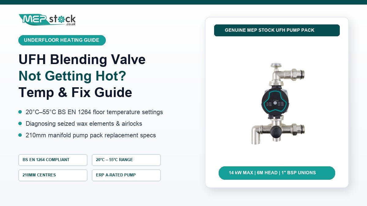
Replace the complete assembly in 20 minutes with our pre-assembled UFH Blending Valve & Pump Set (20°C–55°C). Standard 210mm manifold centres, 1" BSP unions, and ErP A-rated 6m head pump — direct equivalent to Grundfos UPM3 & Wilo Para packs.
Shop UFH Blending Valve & Pump Set →BS EN 1264 Recommended Blending Valve Temperature Settings
Once hydraulic circulation is restored, setting the thermostatic dial accurately protects both the floor finish and boiler efficiency. Under BS EN 1264, surface temperatures in occupied zones must not exceed 29°C (and 27°C strictly for timber and LVT adhesives). Use the commissioning matrix below:
| Floor Construction / Finish | Blending Valve Setpoint | Max Floor Surface Temp | Design ΔT |
|---|---|---|---|
| Ceramic Tile / Natural Stone (Screed) | 45°C – 50°C | 29°C (35°C perimeter) | 7°C – 10°C |
| Engineered Wood / Laminate | 38°C – 42°C | 27°C Max (Strict) | 5°C – 7°C |
| LVT / Vinyl Flooring | 35°C – 40°C | 27°C Max (Adhesive Limit) | 5°C – 7°C |
| Suspended Timber / Joist Spreader Plates | 50°C – 55°C | 29°C | 7°C – 10°C |
Step-by-Step Replacement Protocol for a 210mm UFH Blending Valve & Pump Pack
If diagnostics confirm a seized wax cartridge or burnt-out circulation pump, swapping the entire pre-assembled mixing unit is faster and more reliable than attempting to descaling a corroded brass body:
- Isolate Power & Hydraulics: Switch off the fused spur feeding the UFH wiring centre. Close both primary isolation ball valves and shut off the manifold loop flow meters/actuators to retain water inside the floor loops.
- Drain the Mixing Chamber: Place a catch tray beneath the manifold, open the drain/fill cock on the return bar, and crack the 1" BSP swivel union nuts to relieve residual pressure.
- Verify 210mm Manifold Centres: Measure centre-to-centre between the upper flow bar and lower return bar. Standard UK stainless steel and brass manifolds use 210mm centres, allowing a direct drop-in swap with EPDM flat fibre washers.
- Mount & Wire the New Unit: Hand-tighten the 1" BSP union nuts first to avoid cross-threading, then nip up with pump pliers. Connect the 230V AC pump live, neutral, and earth into the pump output terminals of the UFH wiring centre.
- Purge Air & Set Flow Temperature: Re-open the isolation valves, bleed air through the manifold air vents, set the circulation pump to constant pressure mode (CP2 for 4–8 loops, CP3 for 9–12 loops), and dial the blending valve to your target BS EN 1264 temperature.
Frequently Asked Questions
What temperature should my underfloor heating blending valve be set to?
For screeded floors with ceramic tiles or stone, set the blending valve between 45°C and 50°C. For engineered wood, laminate, or LVT flooring, restrict the flow temperature to 35°C–42°C so the floor surface never exceeds 27°C per BS EN 1264.
Can I turn my UFH blending valve up to 55°C?
Yes, 55°C is safe for low-profile overlay boards or suspended timber floors using aluminium heat spreader plates where heat transfer resistance is higher. Never run 55°C into screeded floors covered with LVT or solid wood.
Why is the pipe before the blending valve hot, but the manifold is cold?
This classic symptom indicates that primary heat is reaching the mixing unit but not passing through it. The top three causes are a seized thermostatic wax element, an airlocked circulation pump, or reversed primary flow and return connections locking the internal check valve shut.
Will the MEP Stock 20°C–55°C blending valve fit my existing manifold?
Yes. The MEP Stock UFH Blending Valve and Pump Set is built to standard 210mm UK manifold centres with 1" BSP unions, making it a direct drop-in replacement for Grundfos UPM3, Wilo Para, Polypipe, Uponor, and generic stainless steel underfloor heating manifolds.